Cell phone call detector


WE PREPARE THE EARLY STUDENT TO FULFILL THEIR FUTURE AND GRADUATES ONE
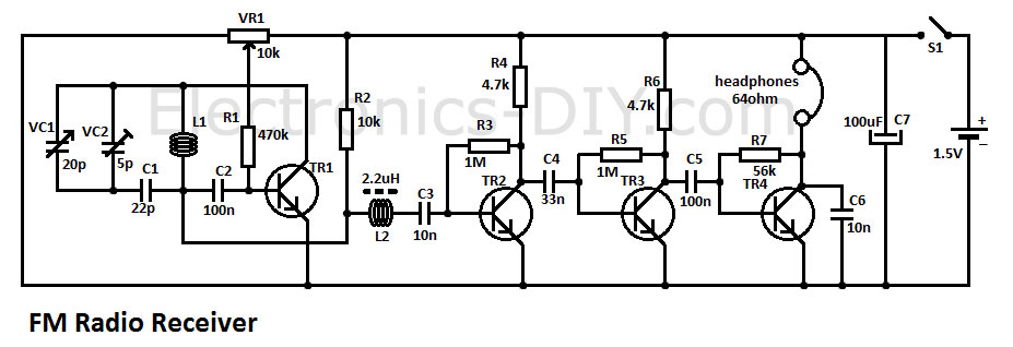
 This circuit was tested and worked properly!
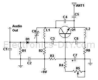
 This tiny transmitter has several "defects": smaller radius of the
service area, lower quality of the sounds and the relatively unstable
frequency. These can be considered as a compromise to easily have your
own transmitter for the time being or as a more positive choice. These
"defects" are only from the perspective of conventional transmission
such as "clear stereo sound to receive anywhere"
This tiny transmitter has several "defects": smaller radius of the
service area, lower quality of the sounds and the relatively unstable
frequency. These can be considered as a compromise to easily have your
own transmitter for the time being or as a more positive choice. These
"defects" are only from the perspective of conventional transmission
such as "clear stereo sound to receive anywhere"